MOTION PLANNING IN ROBOTICS
by
Pooja Nath
98263
An Introduction
Planning is an integral part of our life. It includes choosing the day's outfit based on the weather forecast, figuring out what to eat for breakfast, making a schedule of activities for the day, etc. Planning also occurs on another more instinctual level and includes decisions that we may take for granted, such as choosing to walk around a piece of furniture rather than climb over it in order to get to the door and deciding to take as straight and direct a path as possible rather than going round and round in circles when trying to reach a destination. A large problem in the development of autonomous robots is devising a way to give them the capabilities to make their own plans in a variety of situations. Motion planning refers to the computational process of moving from one place to another in the presence of obstacles.
The degree of difficulty of motion planning in robots varies greatly
depending on a couple of factors: whether all information regarding the
obstacles (i.e. sizes, locations, motions, etc.) is known before the robot
moves and whether these obstacles move around or stay in place as the robot
moves. The different possible scenarios are shown in the following
chart:
|
|
|
|
|
|
|
|
|
|
|
|
The simplest scenario, and therefore the most researched and understood one, is Case I. In Case I, all obstacles are fixed in their positions, and all details about these obstacles are known before path planning takes place. The problem for the robot, which is known as the basic motion planning problem, can be informally stated as getting from a starting point to an ending point without colliding with any obstacles. This problem is usually solved in the following two steps:
The Roadmap Approach
This approach is dependent upon the concepts of configuration space and a continuous path. A set of one-dimensional curves, each of which connect two nodes of different polygonal obstacles, lie in the free space and represent a roadmap R. That is, all line segments that connect a vertex of one obstacle to a vertex of another without entering the interior of any polygonal obstacles are drawn. This set of paths is called the roadmap. If a continuous path can be found in the free space of R, the initial and goal points are then connected to this path to arrive at the final solution, a free path. If more than one continuous path can be found and the number of nodes in the graph is relatively small, Dijkstra's shortest path algorithm is often used to find the best path.
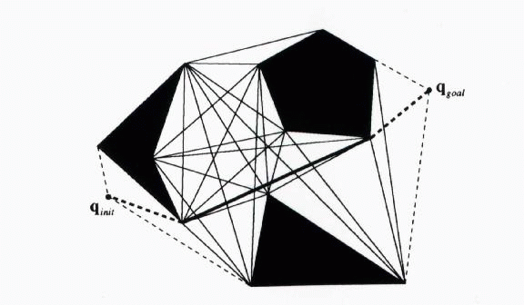
There are various types of roadmaps, the most popular being the visibility graph and the Voronoi diagram. Visibility Graphs are one of the earliest path planning techniques. A visibility graph is shown below. The shaded areas represent obstacles. The solid lines are the edges of the graph and connect the vertices of the obstacles. The dotted lines connect the beginning and end configurations with the roadmap.

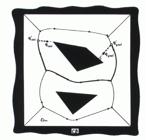
The figure below shows a Voronoi diagram in a configuration space with a polygonal C-obstacle region. This diagram is a planar network of line segments and parabolic curves, which are the set of points equidistant from at least two obstacles. The path generated by this method keeps the robot as far away from the obstacles as possible, unlike the visibility graph.
The Cell Decomposition Approach
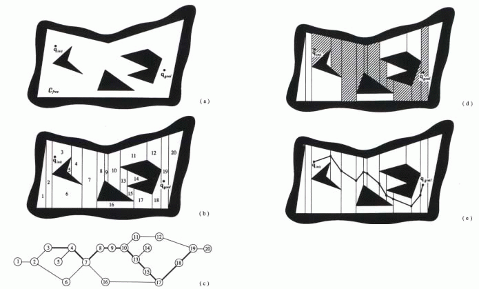
The basic idea behind this method is that a path between the initial configuration and the goal configuration can be determined by subdividing the free space of the robot's configuration into smaller regions called cells. After this decomposition, a connectivity graph, as shown below, is constructed according to the adjacency relationships between the cells, where the nodes represent the cells in the free space, and the links between the nodes show that the corresponding cells are adjacent to each other. From this connectivity graph, a continuous path, or channel, can be determined by simply following adjacent free cells from the initial point to the goal point. These steps are illustrated below using both an exact cell decomposition method and an approximate cell decomposition method.
Exact Cell Decomposition
The first step in this type of cell decomposition is to decompose the
free space, which is bounded both externally and internally by polygons,
into trapezoidal and triangular cells by simply drawing parallel line segments
from each vertex of each interior polygon in the configuration space to
the exterior boundary. Then each cell is numbered and represented
as a node in the connectivity graph. Nodes that are adjacent in the
configuration space are linked in the connectivity graph. A path
in this graph corresponds to a channel in free space, which is illustrated
by the sequence of striped cells. This channel is then translated
into a free path by connecting the initial configuration to the goal configuration
through the midpoints of the intersections of the adjacent cells in the
channel.
Approximate Cell Decomposition
This approach to cell decomposition is different because it uses a recursive method to continue subdividing the cells until one of the following scenarios occurs:
Both exact cell decomposition methods and approximate cell decomposition methods have advantages and disadvantages. The former are guaranteed to be complete, meaning that if a free path exists, exact cell decomposition will find it; however, the trade-off for this accuracy is a more difficult mathematical process. Approximate cell decomposition is less involved, but can yield similar, if not exactly the same, results as exact cell decomposition.
The Potential Field Approach
The potential field method involves modeling the robot as a particle moving under the influence of a potential field that is determined by the set of obstacles and the target destination. This method is usually very efficient because at any moment the motion of the robot is determined by the potential field at its location. Thus, the only computed information has direct relevance to the robot's motion and no computational power is wasted. It is also a powerful method because it easily yields itself to extensions. For example, since potential fields are additive, adding a new obstacle is easy because the field for that obstacle can be simply added to the old one.
The method's only major drawback is the existence of local minima.
Because the potential field approach is a local rather than a global method
(it only considers the immediate best course of action), the robot can
get "stuck" in a local minimum of the potential field function rather than
heading towards the global minimum, which is the target destination. This
is frequently resolved by coupling the method with techniques to escape
local minima, or by constructing potential field functions that contain
no local minima.
A DETAILED DESCRIPTION OF VISIBILITY GRAPHS
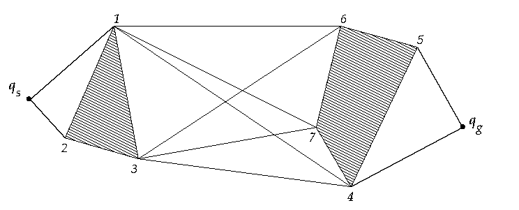
Visibility Graphs have been explained in brief above. Now, some of the well-known algorithms for the construction of these visibility graphs have been presented.
Algorithms for construction of visibility graphs:
1. Brute Force
The most trivial algorithm that comes into mind is to use brute force. The visibility graph can be constructed by considering each pair of vertex and checking if they are visible from each other or not. But, this also happens to be the most inefficient algorithm with time complexity of O(n^3) which can easily be reduced by some book keeping.
2. Variant of Line Sweeping Algorithm
This algorithm improvises over the brute force method
by using a variant of the popular line sweep algorithm. In a conventional
line sweeping algorithm, a vertical line is swiped along the x axis.
However, in this algorithm, instead of sweeping
a line along x axis, we rotate the line and constructs the visibility graph
during the sweep. It does book-keeping by maintaining and updating a tree-like
data structure which stores the information about the edges of the polygon.
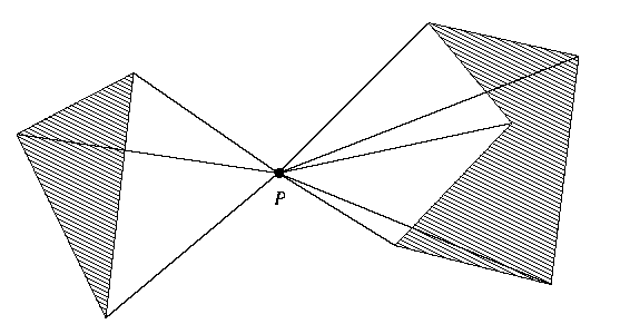
The algorithm takes a vertex in the obstacle space and finds out all the vertices that are visible to it using a rotating ray. It does so for all the vertices, constructing the complete graph in the end.
The pseudo code for the algorithm is given below. VISIBILITY GRAPH(S) takes a set of polygonal obstacles and returns the visibility graph. It uses VISIBLE_VERTICES(v,S), which essentially returns all the vertices visible from v.
VISIBILITY GRAPH (S)
Input: A set S of disjoint polygonal obstacles
Output: The visibility graph G(S)
1. Initialize a graph G=(V,E) where V is the set of all vertices of
the polygons in S, E={}
2. for all vertices v in V
3. do W<-VISIBLE_VERTICES(v,S)
4. For every vertex
w in W, add arc (v,w) to E
5. return G
VISIBLE_VERTICES(p,S)
Input: A set S of polygon obstacles, point p that does not lie in the
interior of any obstacle
Output: The set of all obstacle vertices visible from p
1. Sort obstacle vertices according to clockwise angle that the ray
from p to each vertex makes. Let w_1, w_2, ..... , w_n be the sorted list.
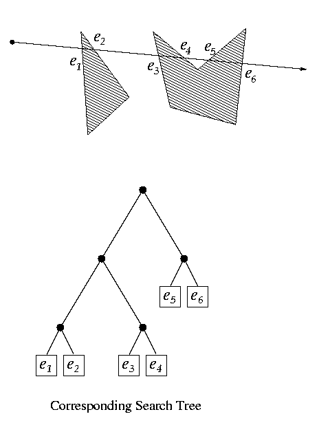
2. Let POX be the ray parallel to x-axis, starting at p. Find the obstacle
edges that are properly intersected by POX, and store them in a balanced
search tree T.
3. W={}
4. for i <- 1 to n
5. do if VISIBLE(w_i) then add
w_i to W
6. Insert into T the obstacle edges incident to w_i that lie on the
clockwise side of the ray from p to w_i
7. Delete from T the obstacle edges incident to w_i that lie on the
counterclockwise side of ray p->w_i
8. return W
VISIBLE (w_i)
Input: A vertex w_i
Output: TRUE or FALSE, depending upon the visibility of w_i from p
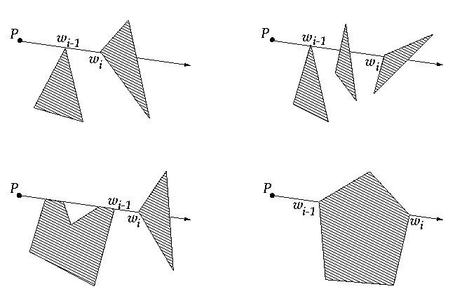
1. if p->w_i intersects the interior of the obstacle of which
w_i is a vertex locally at w_i
2. then return FALSE
3. else if i=1 or w_i-1 is not
on the segment p->w_i
4. then Search
in T for the edge e in the leftmost leaf
5. if
e exists and p->w_i intersects e
6.
then return FALSE
7.
else return TRUE
8. else if w_i-1
is not visible
9. then
return FALSE
10. else
Search in T for an edge e that intersects w_i-1->w_i
11.
if e exists
12.
then return FALSE
13.
else return TRUE
3. Tangent based Visibility Graph
The Tangent Graph algorithm is a path planner developed over a
decade ago In brief, this planner builds a "roadmap" through freespace,
consisting of the
reduced visibility graph, or "tangent graph," of a (bounded) 2-dimensional
configuration space populated by polygonal
obstacles. Given an initial position S, and a target position
T, the visibility graph consists of the union of nodes {S,T, and all
obstacle vertices} and edges {all line segments E connecting pairs
of nodes | E lies wholly in freespace}. The reduced visibility
graph is computed by removing all edges which are not tangent to obstacles
at their endpoints (by definition, endpoints in
freespace are always tangent).
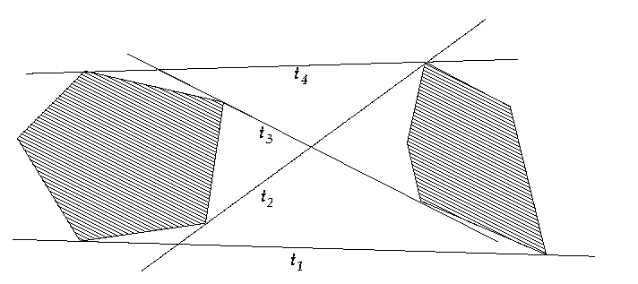
Algorithm to obtain tangents given two polygons:
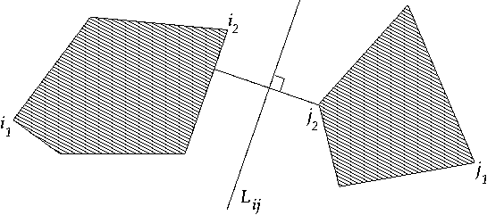
1. Get the two points on the boundary of the polygons which are separated
by the minimum distance
2. Use binary search to get the four vertices i_1, i_2,
j_1, j_2 of P_i and P_j which are the closest and farthest from Lij
3. Start two simultaneous binary searches on the two sequences of vertices
i_1, ..... , i_2 mod n_i and j_1, .... , j_2 mod n_j. Discard
those segments which do not contain P_i or P_j entirely to one side. Redo
this step for all combinations of i_1 .... i_2, i_2 .... i_1,
j_1 .... j_2, j_2 .... j_1 to get both separating tangents and both
supporting tangents
CONCLUSION
This presentation was mainly intended to give an overview of the various techniques adopted to tackle with the motion planning problem. Roadmap Methods, Decomposition Methods, and the Potential Field Methods all happen to be quite simple yet effective. Three common approaches to the building of Visibility Graphs were explained in depth, so as to give a feel of the simplicity of the roadmap methods. Being complete, these are one of the most popular methods for motion planning.
REFERENCES
1. Shortest Paths in the Plane with Convex Polygonal Obstacles, Hans
Rohnert, Information Processing Letters 23 (1986) 71-76
2. Robot Motion Planning, J.C. Latombe, Kluwer Academic Publishers,
Boston, MA, 1991