 |
|
|
 |
|
|
 |
 |
 |
|
|
|
|
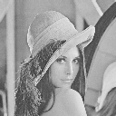
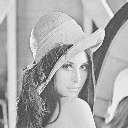
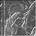
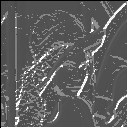
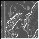
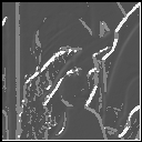
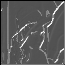
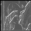
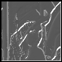
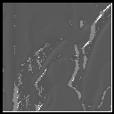
Intensity gradients calculated with different mask size and sigma
together with cumulative histogram of no. of pixels vs pixel grey-value
 |
 |
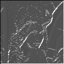 |
| mask : 3x3
sigma : 0.7 |
mask : 3x3
sigma : 0.9 |
mask : 3x3
sigma : 1.2 |
 |
 |
 |
| mask : 5x5
sigma : 0.7 |
mask : 5x5
sigma : 1 |
mask : 5x5
sigma : 1.2 |
 |
 |
 |
| mask : 7x 7
sigma : 0.7 |
mask : 7x 7
sigma : 1 |
mask :7x 7
sigma : 2 |
EXPLANATION:
The progression of images from top to bottom along the same vertical colummn shows the effect of truncation error. These images have been calculated with the same smoothening factor sigma but using different mask size. The progression of the images from left to right shows the effect of increasing the smoothening factor sigma. These images have been calculated using the same mask size but increasing sigma. One can see the effect of increasing the smoothing is reduced noise but it also suffers from lost edges.This is Evident in the 3rd image of the 1st row where the distinctive vertical edge on the left is missed. The effect of truncation is the introduction of a lot of spurious edges.This because of neglecting nonzero contribution from the neighbouring pixels as a result the gradient estimates are erroneous.
HISTOGRAMS FOR SELECTING BEST THRESHOLD
EXPLANATION:
The histogram of the pixel values can be used to find a suitable
value of the threshold.The number of
pixels will reduce as
the threashold is increased. A low threshold leads to an image
with a lot of spurious edges while a high threshold
will lead to missed edges. Thus one needs to trade off these
two effects. At a threshold
value of 0 all the pixels will be considered edge pixels as one raises
the treshold value spurious edges will drop of.It
is expected that near the true value of the threshold only
the correct edge pixels will be selected .Thus the cumulative
frequrency plot will flatten out at those points.Thus one can set the
threshold; to a value;
where the slope of the Cumulative frequency becomes zero or nbsp;
minimum.
Note however
that such a point may not be unique.As in this case where we see that
the distribution of the pixel values are trimodal .Thus
it has 2 zones where the slope of cumulative frequency is near zero. This
shows
that the image has some strong and
moderate edges.
| mask :3x3
sigma : 0.7 |
mask : 3x3
sigma : 0.9 |
mask : 3x3
sigma : 1.1 |
| mask : 5x5
sigma : 0.7 |
mask : 5x5
sigma : 1.0 |
mask : 5x5
sigma : 1.2 |
| mask : 7x 7
sigma :0.7 |
mask : 7x 7
sigma : 1.0 |
mask : 7x 7
sigma : 1.2 |
THRESHOLDED EDGES
| mask : 3x3
sigma : 0.7 threshold : 110 |
mask : 3x3
sigma : 0.9 threshold : 110 |
mask : 3x3
sigma : 1.1 threshold : 110 |
| mask : 5x5
sigma : 0.7 threshold : 120 |
mask : 5x5
sigma : 1.0 threshold : 110 |
mask 5x5
sigma1.1 threshlold : 110 |
| mask : 7x 7
sigma : 0.7 threshold : 122 |
mask :7x 7
sigma : 1 threshold : 120 |
mask :7x 7
sigma : 2 threshold : 115 |