       The difference between Science and Fuzzy subjects is that
                science requires reasoning, while those other subjects
		merely require scholarship.  --Robert Heinlein
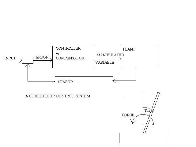
A control system is an arrangement of physical components designed to alter , to change, or to regulate through a control action ,another physical system so that it exhibits certain desired actions or behaviour. Control systems are of two types : open loop control system , in which the control action is independent of physical system output , and closed loop system (also known as feedback control systems).Example of open-loop control system is a toaster,in which amount of heat is set by a human .Example of a closed loop control system is a room temperature thermometer, which senses a room temperature and activates a heating or cooling unit when a certan temperature threshold is reached.
In a closed loop system a sensor measures a control signal. The physical system under control is called aplant. Certain physical forcing signals (called inputs) are determined by the responses of the systems (called outputs).To obtain satisfactory responses and characteristics for the closed loop control system , it is necessary to connect an additional system ,known as a controller , or a compensator , into the loop

In my project of designing a fuzzy logic controller , the object is to maintain physical variables (position and velocity of an inverted pendulum ) within a certain limit. It will try to follow or track some function . The plant is the simplified version of inverted pendulum . The differential equation describing the system:
           2          2
    m.l.l.d (theta)/dt +(m.l.g) sin(theta)=u(t)
    where
    m=mass of the pole located at the tip point of Inverted Pendulum
    l=length of the pendulum
    theta=deviation angle from vertical in the clockwise direction
    u(t)=torque applied to the pole in the counterclockwise direction
    t=time
    g=gravitational acceleration constant
You can also see the original
proposal for this project.
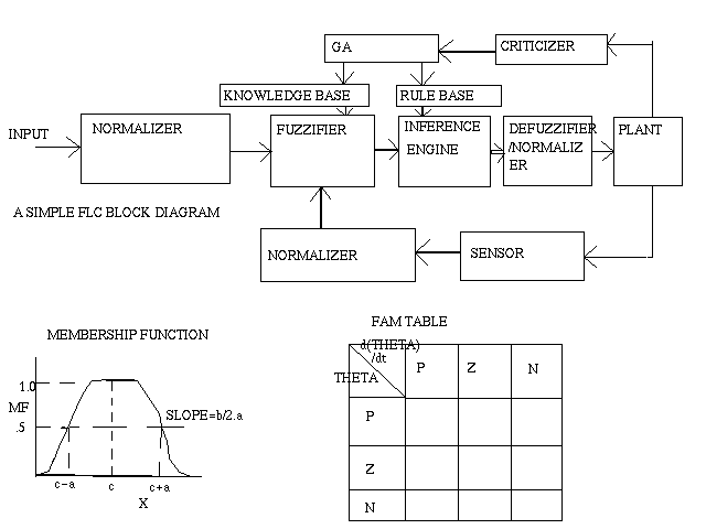
In the project I have changed the first three parameters mentioned above by means of a simplified version of Genetic Algorithm.I have not made the membership functions of output variable adaptive because then defuzzification would become complicated.The GA will make the rule base and the knowledge base adaptive.

The equation of the membership function shown in the figure :
                               2 b
              y=1/(1+[((x-c)/a) ] )
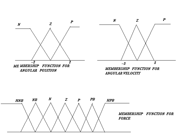
So it is seen that every membership function can be expressed by three parameters a,b,c.The blank boxes would be filled in by the consequent part of each if-then rule. The table is to be altered by GA according to the performance of the controller.Position and angular velocity are the two inputs and force is the output for the fuzzy logic controller.
Previously generation of membership function and FAM table was mainly done either iteratively or by trial and error method or by human experts.A task such as this is a natural candidate for GA.Ga will attempt to create membership functions and FAM that will cause the controller to operate optimally.
Recently, work has been done using GA's to do each of these tasks separately.Karr , for example has used a GA to generate membership function for pH control process and Cart-Pole problem. Such work has shown GA's ability to successfully create the individual parts of a FLC , but since membership function and rule sets are co-dependent,using a hand designed rule set with a Ga designed membership function or a hand designed membership function with a GA designed rule set does not use the GA to its full advantage.Thus the use of GA to determine both membership functions and rule base simultaneously for an optimal and near optimal controller is the main objective of this work.
step1: At first two state variables are defined.In my case , they are angular position and angular velocity (degrees and dps).
                       x1=theta
	               x2=d(theta)/dt
step2: Then two state equations are written.In my case they are:
               dx1/dt=x2;
	       dx2/dt=(g/l)*sin(x1)-(1/m.l.l)u(t)
Here certain assumptions have been made like :
               l=g
               m=180/(3.14.g.g)
Now the matrix Difference equations become ,
               x1(k+1)=[x1(k)+x2(k)]*sampling interval
	       x2(k+1)=[x1(k)+x2(k)-u(k)]*sampling interval
	       k=one sampling instant
	       k+1=next sampling instant
step3 : Different individuals of the first generation are formed with the help of C Library function RANDOM().They are represented by binary chromozome. Each individual consists of parameters for the membership function (a,b,c) and consequent part of each rule.Each of the membership function parameters is represented by 4 bits. there are 8 possible consequent parts ( e.g NB,N,Z etc). They are represented by 3 bits. So each chromozome consists of 51 alleles. Each generation has 100 individuals.

step 4: Next, decoding is done for each parameter in the chromozome.In this simplest form of GA I have specified the search space for each parameter. (amax,amin etc).The decoding of membership function parameter is done by:
    Ci=Cmin+{(b/(pow(2.L)-1))*(Cmaxi-Cmini)}
    b=decimal equvalent of a binary number
    Cmax and Cmin define the search range.
    L= length of the string
For rule consequents only b is found out.Each integer represents one consequent in a rule. (e.g 0 represents HNB, 1 represents Nb etc).
step5: The input and output spaces are fuzzified .
step6: Nine rules ,representing control actions are entered into the FAM table
step7:Ten initial combination of values of velocity and position are taken to test the performance of the controller for each individual.
step8 : Now for each individual with each initial value simulation of the control problem is done for 10 iterations.
step9 : Firing strength of each rule is determined.
step10:Defuzzification is done by height method.Each iteration gives one value position and angular velocity.
step11: Initially all the individuals were given a point zero. If after each iteration if the position and velocity is not lying within the specified range (+-2 d or +-5 dps) the point of the individul is deducted by ther sum of squared difference (SSD).So the aim of the ga is to reduce the SSD.
SSD=sqrt([(mod(theta))-2]**2+[(mod(d(theta)/dt))-5]**2)
step 12: Finally we get the point of each individual . We sort them according to their points. The first 50 individuals are only allowed to reproduce. The best individual is duplicated thrice and inherited to the next generation.
step13 : The rest of the individuals in the next generation are formed by recombinations. I have chosen two individuals randomly.The probablity of recombination is seventy percent.I have filled 70 bits of a 100 bit register by 1. With the help of this register and C library function random(), I have determined whether mating would be possible between two randomly chosen individuals or not.If mating is possible I have randomly chosen the position of recombination .I have done single point recombination. Here parent1 and parent2 produce child1 and child2.

Recombination is done by Monte-Carlo method
step 14:similarly mutation is done.The probablity of mutation is 3%.
step 15:Finally the motion of the pendulum is shown by the graphics Xdraw.
if you want to see how the average fitness improved click here
if you want to see how the minimum fitness improved click here
Here is different angular positions and velocity for INVERTED PENDULUM click here
| \ | P | Z | N |
|---|---|---|---|
| P | HNB | HNB | HPB |
| Z | HNB | HNB | NM |
| N | NM | NM | HPB |
       angular position horizontal
       angular velocity vertical