 |
 |
 |
ME 768
ARTIFICIAL INTELLIGENCE IN ENGINEERING
YEAR 1999-2000
3D RECONSTRUCTION FROM MULTIPLE IMAGES
INSTRUCTOR
Dr. AMITABHA MUKHERJEE
INDIAN INSTITUTE OF TECHNOLOGY
KANPUR
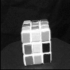
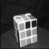
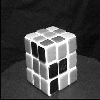
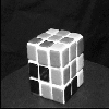
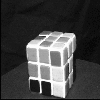
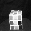
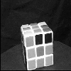
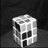
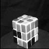
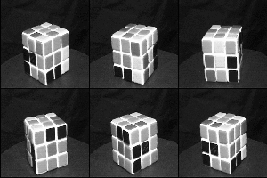
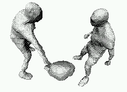
The aim in this project is to use a turntable or a robot using which we can obtain photographs of a given object from known angles. We aim to reconstruct and model these 2D images to obtain the 3D form of the object, which will be developed and exhibited in OPENGL. Thus our project does not limit itself to giving the user the freedom of viewing the object at any angle and in any orientation but provides him with the complete model in space. 3D reconstruction and modelling is used in many fields like Virtual Reality, recognizing and manipulating objects etc. .
Nowadays various algorithms are available which do not require even the camera positions to be known. We intend to modify our project so that it will reconstruct the image even if camera positions are not known.
 |
 |
 |
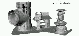
International Conference on Recent Advances in 3D Digital Imaging and Modelling
Ottawa,Ontario
page no 6 BACK TO TOP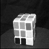 |
 |
 |
 |
 |
 |
 |
 |
 |
 |
 |
 |
 |
 |
 |
 |
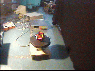
1. Keep the object stationary while rotating the camera around it.
2. Keep the camera stationary while rotating the object about it's center.
The first method gives better results because the object is stationary and hence any point on it will remain in the same relative position w.r.t the stationary light sources. Hence we can get Lambertian images directly.However it is difficult to rotate the camera in a circle with high precision. Hence we use the second method.
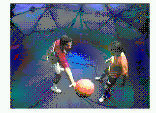
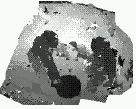
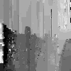
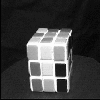
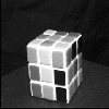
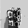
We define a depth map of an image as another image in which the points farther from the camera are shaded by progressively lighter shades, thus depicting the 3D characteristic of the image. We need two or more images of the object for constructing the depth map (range image).
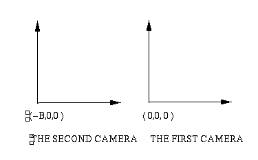
y1 = Y*f/Z y2 = Y*f/Z
Where f is the focal length of the camera.
Suppose we know that for a point (x1,y1) in image 1, corresponding matched point in image 2 is (x2,y2). Then we can define a term DISPARITY which is the distance between the two points (x1,y1) and (x2,y2).
DISPARITY d = (x2,y2) - (x1,y1) = B*f/Z
Hence if we can obtain d,we can find out Z, the depth of the point (x1,y1) in image 1.
Given a point on the first image, it's match is constrained to lie in the epipolar line formed by the point in the second image. Assuming the two images to be stereo, for a given point (x1,y1) and ASSUMING a disparity d, we can obtain the corresponding point (x2,y2) in the second image. Then we observe whether (x1,y1) and (x2,y2) are matching or not by using two criteria
1) Intensities should match. Since images are lambertian.
2) Their order in the epipolar lines should be the same.(Ordering Constraint)
Defining cost function as
C = Differnce in pixel intensities of (x1,y1) and (x2,y2).
Our aim is to find d for each (x,y) for which C is minimised.
The algorithm is as follows.
1) All epipolar lines for the image are stacked together. Thus our aim is now to find the SURFACE with minimum C.We associate a capacity C' to each point (x,y,d), where capacity is directly proportional to C.
2) We add a source and a sink across the surface and treat it as a flow problem in a graph. The points where the flow is maximum are the ones for which capacity is minimum. Hence by solving this flow problem we directly get the desired iso surface for which C is minimum and hence disparity obtained is optimum.
 |
 |
 |
Consider the following diagram.
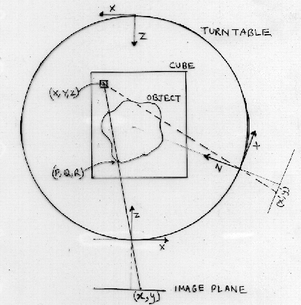
Next we divide the big cube into many small volume cells,called voxels. Each voxel will be denoted by a point defined in the coordinate axis of the first camera position. Let us assume a voxel denoted by (X,Y,Z). Our aim is to find out whether this voxel is inside the object,at the surface or outside it.Thus each voxel is associated with an implicit function value that describes it's state w.r.t the surface.
Given a voxel (X,Y,Z) we can calculate it's projection (x,y) on the image plane. We can also obtain it's disparity Dv from the value of Z. However the disparity value Dvsm obtained from the depth map at (x,y) depends on the visible surface {point (P,Q,R) in the figure}. We define the implicit surface function f(X,Y,Z) as
f(X,Y,Z) = Dv -Dvsm
For other images, the coordinate axis is shifted s.t. the other camera position
also lies at the origin. The implicit function value for (X,Y,Z) is calculated by
transformation to the new frame and is added (with appropriate weight) to the
previous value. Voxels near the surface have very low values of f(X,Y,Z) and only
these are considered for surface generation.
@Article{Roy/Cox:1998,
author  ={ Roy,Sebastian and Cox,Ingemar},
year    ={ 1998},
keywords={ depth map,stereo images,maximum flow,disperity map},
institution={ NEC Research Institute, 4 Independence Way, Princeton},
title   ={ A Maximum Flow Formulation Of The N-Camera Stereo Corresponding Problem},
journal ={ Sixth International Conference on Computer Vision},
month ={ January},
pages=      {492-500}
e-mail  ={ roys@IRO.UMontreal.CA},
www     ={iro.umontreal.ca },
annote  ={
 This paper describes a new algorithm for solving the N-camera stereo correspondence
 problem by transforming it into a maximum flow problem. Once solved, the minimum cut
 associated to the maximum flow yields a disparity surface for the whole image at
 once. This global approach to stereo analysis provides a more accurate and coherent
 depth map than the traditional line by line stereo.
 	     -- Vikas Kataria 2000
        }}
@Thesis{Rander:1998,
author = { Peter Rander},
year = { 1998},
keywords = { Image based modeling, Shape recovery, visible surface models,
general camera model, volumetric fusion, decimation of meshes, range maps},
institution= { Robotics Institute, Carnegie Mellon University},
title = { A Multi Camera method for 3D digitization of Dynamic, Real World events},
number = { CMU-RI-TR-98-12},
month = { May},
pages = { 136},
www = { rander@cs.cmu.edu},
annote ={
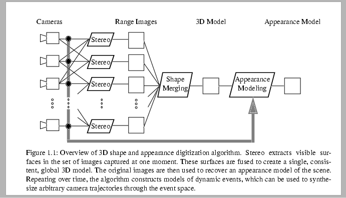
This 3D digitization method decomposes 3D shape recovery into the estimation
of visible structure in each image frame followed by the integration of visible
structure into a complete 3D model. Visible surfaces are extracted using
multibaseline stereo algorithm. Stereo computed range images are then
integrated within a volumetric space using a novel integration strategy . Each
range image is converted into a 3D mesh amd then into an implicit surface
embedded into the volumetric space by encoding the signed distance between each
3D volume sample ( voxel ) and the 3D mesh. Multiple range images are
integrated by accumulating the signed distance at each voxel. The resulting
global surface model is then extracted by applying the marching cubes implicit
surface extraction algorithm.
- Vikas Kataria ( 12/2/00) }
}
   @Article{Fitzgibbon/Cross/Zisserman:1998,
author  ={ fitzgibbon,Andrew w./Cross G. and Zisserman A.},
year    ={ 1998},
keywords={ projective geometry, fundamental matrix, trifocal tensors, camera
            matrix, sequence invariants, image lines, octree growing },
institution={ Robotics research Group, Dept. of Engg. Science, University of
           Oxford},
title   ={ Automatic 3D model reconstruction for turntable sequences},
journal ={ Structure and Motion fron multiple images in large scale environments,
           Lecture notes in computerscience , Springer 1998},
e-mail  ={ awf@robots.ox.ac.uk,geoff@robots.ox.ac.uk,az@robots.ox.ac.uk},
www     ={ http://www.robots.ox.ac.uk/~vgg},
annote  ={

This paper describes a system which, given a sequence of images of an object
rotating about a single axis generates a textured 3D model fully automatically.
The technique described here requires no prior information about the cameras or
scene and does not require that turntable angles be known.
From an analysis of the projective geometry of the situtation, it is shown
that the rotation angles may be determined unambiguously and that camera
calibrations, camera positions and 3D structure may be determined to within a
two parameter family. An algorithm has been implemented to compute this
reconstruction fully automatically.
        The paper considers the motion of the camera in a perfect circle about
the object to implement the 3D model. The two motions are considered equivalent.

        Supratim Ray (12.1.2000)
        }
 }
@Article{Bloomenthal:1994
  author=       { Bloomenthal,Jules},
  year=         { 1994},
  keywords=     { polygonization, implicit surface},
  institution=  { The University of Calgary, Calgary, Alberta},
  title=        { An implicit surface polygonizer},
  publication=  { Graphic Gems IV edition},
  pages=        { 324-349},
  www=          { Not Availiable}
  annote=       {
		                  An algorithm for the polygonization of implicit
surface is described. The paper also compares different algorithms of polygonization
of implicit surfaces.
	          - Vikas Kataria,April 2000      }