In the header, each identifier used in the story is declared to be of a certain type.
<EntityType> <Identifier>
Then their positions are specified. It is assumed that the posiitons of objects is specified in precise coordinates and when it is
specified as the vicinity of another entity, there is no ambiguity.
<ID of entity> at <<RoomName coordinates>/<AnEntity>>The initial information also includes containership information. This is the of information conveyed by 'in', 'on', etc. The format is as follows:
<ID of entity> on/in <AnEntity>
The grammar of actions is in the format as follows:
<ID of doer> <Action> [<Parameter1> <Parameter2> ...]The Action may be atomic or composite. Atomic actions include 'goto',
'speak', 'face', 'pick', and so on. Composite actions, depending on the
current state, involve the performance of some atomic actions. For example,
jack: pickup MidnightsChildren
This would probably involve first moving to the table on which the copy of Midnight's Children
is lying and then picking it up. These are two atomic actions.
To make the content of the story, if not the style, closer to natural Action Interpolation is performed. In a nutshell, common (composite) actions which actually consist of atomic actions are specified as a single action. Action Interpolation replaces this composite action with a sequence of atomic actions.
After interpolating for each geographic motion in the scene, the path is computed and encapsulated in an object. Internally, this object stores the path in a file owing to the large quantity of data involved.
The result is a list of atomic actons with all the required data (positions, orientations, paths, etc) in a file. The camera placement module now uses this file to generate the camera parameters for each frame and stores this in another file.
Finally, the Animation module uses these two files to generate the output with the appropriate views.
One of the tasks is to translate a directive like
A : move to t1
into an actual path from the present location of A to the specified location t1.
This involves avoiding collisions with obstacles on the path and having some degree of error forgiveness
which lend a higher level of realism.
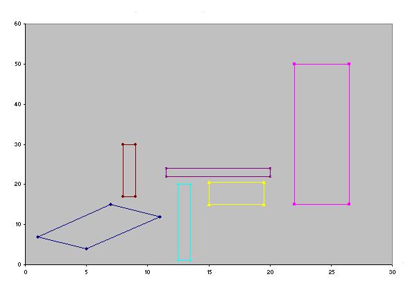
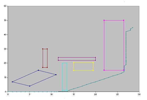
The standard method of visibility graphs shall be used and information about convexity of each entity shall be encapsulated in that object itself and not left to be determined at run-time. The following is an illustraton to elucidate the process
A visibility graph is a graph where the nodes are the vertices of the polygonal obstacles and an edge is drawn from one vertex to another if the edge is "visible". An edge is visible if it does not intersect any obstacles. Once the static graph is constructed, goal and origin vertices are added and their visible edges are computed. This graph can then be searched for a shortest path between the origin and goal.
- Create a grid and superimpose it on the configuration space. For every edge in every obstacle, check for intersection against grid lines. For each of the two endpoints and each intersection point, add it to the region that it belongs to. The intersection points are shared by more than one region.
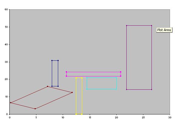
- For every region construct the visibility graph for points in that region, including shared points. In other words, for every pair of points in the region, that are "visible", add an edge between them in the global visibilty graph.
- In addition to the points shared by two regions when an obstacle overlaps those regions, we need "glue points" in order to make sure that the set of local visibilty graphs is globally connected. Otherwise, empty regions can disconnect sections of the global visibility graph. At a minimum, we need to add a point to the corners of every region.
- Once the static visibility graph is constructed, operations such as adding a vertex to the graph, adding an obstacle, or removing an obstacle. For example, to add a start or goal vertex, find the region that contains the vertex, and find the visible edges from the vertex to the local points maintained by that region. Add the vertex and those edges to the visibility graph.
- In order to plan a path, we insert the start vertex and the goal vertex, and then search the global graph for a path between the two.
Images from Lozano, Perez:1996
 |
 |
 |
 |
 |
 |
| 
|
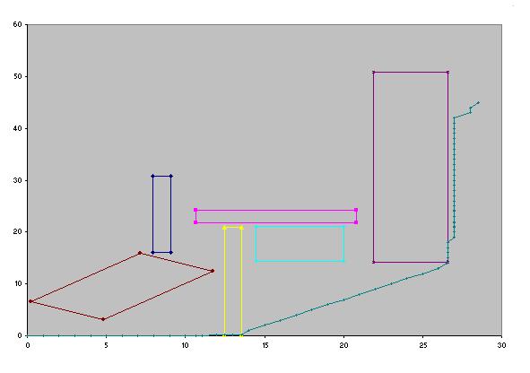
The resulting path contains a number of sharp corners. These will be removed by using a snake which has the path produced by the visibility-graph process as its initial configuration. Internal energy is a function of the length and sharpness of the curve. External energy is due to the potential fields of the obstacles.
In our case we have assumed the obstacles to be rectangles, which can be oriented in any direction. The moving object is assumed to be in the form of a circle.The size of the grid with which we decompose the configuration space depends upon the size of the configuration space i.e. the larger the configuration space the larger will be the size of the grid.
For searching the path we have made use of A* algorithim. The heuristic function in our case is the distance between the current node and the goal node. Compared to other search techniques A* algorithim works best in our case because the search environment is known before hand. The alternative search technique was that of uniform cost search technique(breadth first) but this is computationaly intensive, hence we opted for A* algorithim.
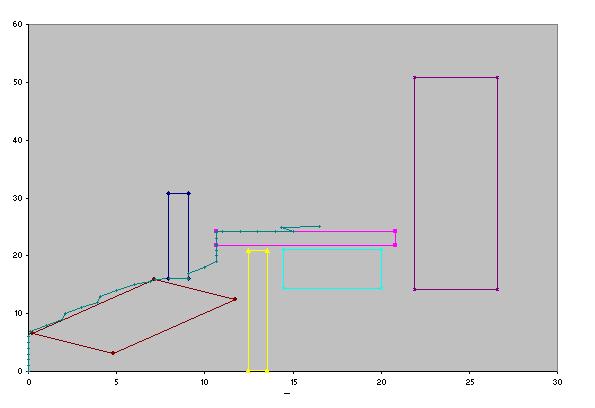
For smoothing of path we have made use of snakes. Snakes consists of control points, effectively connected by straight lines. In our case these control points are nodes along the path. One of the chief virtues of snake representations is that it is possible to specify a wide range of snake properties, through a function called the energy function by analogy with physical systems. So by specifying an appropriate energy function, we can make a snake that will evolve to have particular properties, such as smoothness. The energy function for a snake is in two parts, the internal and external energies. Thus
  E          =   E          +  E
snake          internal      external
The internal energy function in our case is
          N
E = K1 * SUM (square of distance between control point i and i-1)
	 i=1
Here N is the number of control points and K1 is arbitrary constant defined
by the user. To find the force acting on each control point the above
expression needs to be differentiated.
The elastic force on the i'th control point has force in x and y direction given by
F              =   2 * K1 * ( (x   - x )  +  (x   - x ) )
elastic_X,i                    i-1   i        i+1   i

F              =   2 * K1 * ( (y   - y )  +  (y   - y ) )
elastic_Y,i                    i-1   i        i+1   i
Analysing the above expression, it can be seen that force on each control point pulls it towards it nearest neighbours. This is represented schematically as shown below.
      |            _
      |            /|
  i-1 o           /
       \         / Elastic force on i along this line
        \       /
snake -> \     * <- half way between i-1 and i+1 points
          \   /
           \ /
            o- - - - - -o- - - - -
            i          i+1
Hence it is clear that such a force applied to every control point will
pull the snake inwards and will pull the control points into line with
one another, smoothing the snake.
Once we have an expression for the force, we can implement the dynamics of the snake simply by moving each control point by an amount proportional to the force acting on it. The transformation equation is therefore
 x    +   K2 * F            ->   x
 i             elastic_X,i       i
and a similar equation for Y. K2 is another user-defined constant, which determines the rate at which a point moves for a given force.
While performing such a transformation care should be taken such that control points should not enter the obstacle space. Hence we define the external energy of the snake such that the force acting on the control point pulls it away from the obstacle space. In our case we have made use of the potential energy function as our external energy.
       M
E =   SUM( 1/di)-(1/dg)2
      i=1
Here di represents the distance from the obstacle space, and
M is the number of obstacles. dg represents the distance from the
goal.
The expression for force is obtained by differentiating the above expression.
Due to the work of Salesin et.al. there exists a precise language in which the configuration of cameras and lights can be specified. At every stage, the story has a focus which is the locale where the story is unfolding. Assuming this to be a single region, the camera continuously configures itself based on some action-specific idioms which are produced automatically from the storyline.
Camera Control
Here is an example of an idiom used to depict an interaction between two persons.Images from Salesin et.al:1996
Fragments are the atomic elements of a movie. Some of the fragments defined
by DCCL are: The aim of the camera planning module is to give the
animation a more enhanced, dramatic look. To be able to do this the principles
of cinematography are used. Each film is broken down into parts that carry the
same storyline or theme.This is called a scene.In other words in a scene an
actor does a simple set of activities,like a man picks up a book, goes to
a woman, gives the book to her and has a little chat with her.Now this scene
is composed of some basic actions like picking, moving, giving, talking, and
going back. Each of these activities has a distinct requirement of camera
movement and this is met by specifying Idioms for each of these
activities. The Idioms enclose the necessary information about the type
of camera-work for that particular activity.Heuristics are implemented in
the Idioms themselves. They are simple rules like for example, maintaining the
relative motion of actors on screen by letting the camera be on one side of
their path.These Heuristics are the gist of what the cinematographers have
developed and by implementing some of them we are making use of that
knowledge. As the story progresses these Idioms are passed on the
details of the activity and they generate exact specifications of camera for
that activity including its velocity, path, field of view, direction and the
type of fragment it is. Ultimately, the scene will be rendered using the OpenGL library.
The merits of the initial plan of using Java3D were outweighed by its extreme complexity.
The current design allows the story parsing to be done on a remote server along with NLP.
The Animation module can run on the local machine.
The main feature of the animation is a the key-frame modelling of the gait of the human
agents in the scene. Here is the result: The blue coloured box in the middle of the man indicates the centre of camera.
The basic framework for the animation is as follows. The trace is read by the
controller an action at a time and the objects involved in an action are
initialised to their initial states. At regular intervals of time, each
object in the scene is asked to render itself by a coordinator. On recieving
such a request, based on its current state and the action it is involved in at
that moment, each object unpdates its state and renders itself on the
viewport.
The camera is treated like yet another object in the scene. It updates itself
by asking the controller for its next configuration. Then it performs the
required GL transformations to render the scene for that camera configuration.
Animation