ME751 Project Proposal
Computer Aided Engineering Design ME 751/451 Jul-Nov 99
-:Mukerjee
Extraction of Toleranced CAD Models from Digital Images
|
Gagan Deep Arora (96095)
Ravi Prakash Srivastava
(96226)
Indian Institute of Technology - Kanpur : September 1999
Contents
Motivation
Actual Design Process involves assignment of shapes and their dimensions which
in turn serve as the guidelines for the manufactureres, developers, users, and
the designers themselves. The various stages of development of a design,
particularly the machinig fabrication and testing involve considering it as
an approximation in the sense of defining tolerances for both shape and size
parameters. These tolerances are inevitably encountrered due to the limitations
of each of the stages of the design and development process. It is therefore
only essential that the designer be equipped with tools which allow him to
design and test with real-life considerations of tolerances.
The present-day CAD tools have little to offer in this area and much work needs
to be done before tolerances can be handled by CAD platforms which can
identify shape classes rather than rigidly considering shapes alone.
The present work is a step in this direction wherein we attempt to extract
toleranced CAD models from images of simple, yet representative, 3-D models
and providing a shape class for the identified shape.
![[Back to Top]](images/icons/first.gif)
![[Previous]](images/icons/prev.gif)
![[Next]](images/icons/next.gif)
![[Last]](images/icons/last.gif)
![[Home]](images/icons/home.gif)
![[Information]](images/icons/info.gif)
Example: Extraction of Tolerance model from snapshot of letter object 'L'
The Image taken is preprocessed for improving the brightness and contrast
properties of the image so as to facilitate edge detection for the object which
is essential for defining the shape boundary.
.

.
Figure: The Snapshot of object in full color and converted to greyscale.
.
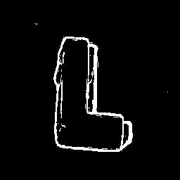
Figure: Edge detected images - from greyscale image (left) and with pixel inversion with
shadow edges removed (right). To be used as a start-point for the shape class
definition algorithm.
As observed in the above edge detected image, the sharpness and the strength
of the edges depend on the orientation of the edges with respect to the camera.
Hence, also, when the same object is viewed from different angles, the shape
definition may vary depending upon the light intensity and the relative
positioning of the edges. Thus, several snapshots need to be taken of the object
and each would then be identified with a set of vertices and edges. Some
admissiable value of tolerance would decide the extent of deivation of these
vertices/edges from the corresponding vertices/edges in the various images.
Past Work
Identifying Vertices and Edges
Extraction of vertices and edges in the input image is a primary concern of the
project work. The entered image can, at best (in ascii format), be
identified as an array
of numbers ( in the range 0 to 255 for greyscale format wherein each pixel is
represented by a single number ).
Identification of straight lines and curves would be based on techniques similar
to or directly based on Hough Transforms. Binarised edge-detected images would
be traversed along the points of high intensity values, the path being guided by
the vicinity crieteria for high-intensity points. Traversal for a particular
edge would be ensured by the continuity of the high-intensity points.
The exercise would essentially identify edges and hence the approximate vertices
for the image.
The accuracy of the edges detected would depend on the choice of the
"freedom-to-deviate" factor. A high value of this factor would result in gross
approximation and loss of information while too low a value for this factor
would encourage high level of noise in the extracted model.
Defining Shape Classes from identified set of edges and vertices
The edges, as obtained from several such images of the same object would
be used to construct shape class for the object by recording the effect of
induced deflections in vertices' position, edges' position(and angle) or both.
Thus, there would be primarily two methods of inducing disturbances in the
image and accepting or rejecting the so produced images based on the range of
tolerances allowed.
- Disturbance in vertices - These would consist of allowing each vertex to
deviate slightly from its original position and then noting the changes thus
produced.
- Edge disturbances - In this, the edges would be allowed certain amount of
extension/compression and also angular deviation.
Sample Input and Expected Output
The input consists of edge detected binarised images like the one show in
example. For each object, the input would be several such images actually
taken from varying angles.
The problem would be taken up for an increasingly complex set of input data.
It is worth noting that the problem of extracting CAD models and assigning
tolerances would be an increasingly difficult one as we consider object from the
range of I to Q and similar such complicated ones ( with several edges and
particularly "holes").
The above snapshots were taken under a single light source and thus contain
severe shadow effects. This is undesirable for obvious reasons and fresh
images need to be taken for each of these.
Also, the change in angular orientation for the two images of 'Q' is drastic
and shall not be helpful in defining shape classes. The different images need to
be taken such that the major shape of the object is preserved. One such method
would be taking the snaps from ovrhead.
The output would be a set of shape classes which shall be all be different
in the strict sense of CAD modelling as used today, but each of these would
be identified as the same object from where they originated. Moreover, based on
these shapes, as mentioned in the methodology, more shapes would be generated
by inducing vertex and edge disturbances. All these again, would be identifiable
as the same object.
Limitations
- The current study shall be kept limited to shapes which can be approximated
with straight lines and second order curves, particularly circular arcs, for the
sake of simplicity. The results can be later extended to include higher order
curves and other shapes as well.
- The work attempted here would be limited to taking only edge detected
images as inputs, in pgm ( greyscale ascii / raw )format. The image processing
part is left to be
done by standard image processing utilities available. We make use of GIMP
for the preprocessing needs.
- Presence of Shadows in the input image would crucially affect the results
since the edge detection algorithms would identify these as shape boundaries.
It is therefore required to take care to minimise shadow while taking the images
( should be taken in diffused sunlight ) and required preprocessing
should be allowed to eliminate any present shadows.
References
- Goswami,A. Identification of Partially visible Shape Classes, July 1999
Indian Institute of Technology, Kanpur, Dept of mechanical engg.
- Two
Dimensional Image Processing
- ICRA'98 Article
Abstracts
May 16-20, 1998 in Leuven, Belgium
-
Srinivas Akella's Research
The references at the moment are not annotated in the standard
format. They serve only as indicators to the reference we took. Later in the
study, the bibliography shall be completed
Source Snaps as taken by the digital camera.
This proposal was prepared by Gagan Deep Arora and Ravi P.Srivastava as a part
of the project component in the
Course on Computer Aided Engineering Design
in the July-December Semester, 1999.
(Instructor :
Amitabha Mukerjee )
[CAED COURSE LECTURES HOME PAGE]