INTRODUCTION
Tring Tring...Tring Tring... the phone
rings,one picks up the reciever and calls out into it
....Hello!...irrespective of the caller! A hurried exchange apprises
one of the identity of the caller , and conversation which ensuses is
happily oblivious of the separation between the speakers . Or perhaps
what strikes us - the hostelities much more is the clear voice of our
families providing us with the words of comfort and encouragement , or
perhaps the sweet , seranading voice of each of our girl friends -
when on the phone, constantly titillate us by reminding of relativity
- time seems to fly much too quickly , while those waiting for their
turn , find longer than an unbiased clock would indicate. A
businessman or an executive making deals , or journalist reporting to
his newspaper , a student contacting his professor for advice ,
gossiping amongst friends or perhaps even more frivolously , a wife
calling up her husband every hour to keep a tab on him!
Amid this
gamut of emotions , diversity of cultures and communication across the
miles , what was probably most striking was how we overlooked the
mediums, the instrument the telephone - the product of the marriage
between the disciplines of Electrical & Mechanical engineering.
Thus, an examination of this device , which in its plethora of styles
and forms , has proliferated to almost every home ;is the objective of
our present discussion.
MECHANICAL SYSTEM
BACK TO TOP
DIALLER SYSTEM
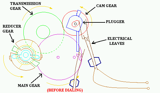
DESCRIPTION OF DIALLER COMPONENTS
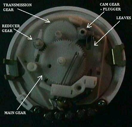
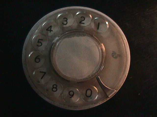
1. DIAL
It is a circular plastic disc with small circles cut along its periphery
, through the finger can be passed to actuate the diallling. The sheet of numbers is pasted to the base below it , which remains fixed.
2. MAIN GEAR
It is directly connected to the shaft on which the dial is mounted and essentially transmits to the rotation of the dial to the internal dialling mechanism.
It has two small projections, the pushers; and has 66 teeth.
3.DIALLER SPRING
It is a torsion spring which is connected between the dial and the base. It is this spring which results in the return of the dial once a digit has been dialled.It further provides a limit to the dial by becoming tightly wound around the
shaft.
4. TRANSMISSION GEAR
It is a system of two gears mounted on a single shaft. The smaller one acts as the pinion to the MAIN GEAR
while the larger transmits this motion to the
CAM GEAR
and the REDUCER GEAR.The pinion has 11 teeth
and the gear has 64 teeth.
.
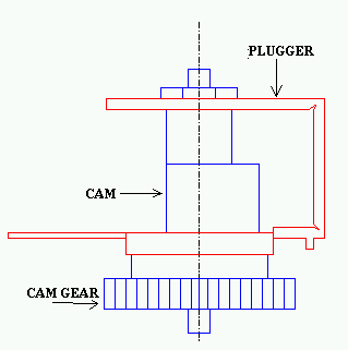
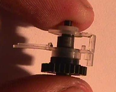
5.CAM GEAR & PLUGGER
The cam gear consists of a gear and a cam on acommon shaft. The gear meshes with the TRANSMISSION GEAR
while the cam transmits the pulse motion to the electrical contacts.
The plugger manifests itself in holding one of the electrical plates fixed, so that the motion of other would lead to an alternating loss and maintenance of contact.
The cam gear has 28 teeth.
6. ELECTRICAL LEAVES
The electrical leaves are in the form of leaf springs, which under normal
conditions stay together. One of these is in contact with the cam of the
CAM GEARand thus moves in accordance with it
.
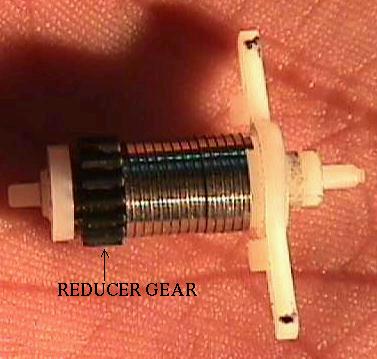
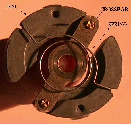
7. REDUCER GEAR
It consists of two separate half discs which are joined together by a crossbar
, which allows the discs to be separated.Thsese are held together by a spring .This arrangement accomodates one of the reducer gear which transmits motion
to & from the reducer.The reducer is enclosed within a circular ring, the
inside of which is metallic.The reducer gear has 16 teeth.
BACK TO TOP
MECHANISM OF DIALLER
The dialling mechanism is that part of the telephone instrument which
converts the information of the dialled telephone number into electrical impulses which are thus transmitted to the exchange for the required connection.
The impulses as mentioned above are electrical in nature and are generated
by the alternating loss of contact and making of contact of the electrical leaves. The contact is broken as many times as the dialled digit.( the explanation of which will follow shortly)
The electrical leaves act as leaf springs, which are prestressed such that normally remain in contact. The inner leaf presses against the cam throughout
the dialling cycle and thus as the cam rotates , the inner leaf oscillates along with it. If the outer leaf is free to move , it would remain presses against
the inner leaf , thus moving along with it and maintaining electrical contact.
But , if the outer leaf is held back physically;as the inner leaf oscillates it would alternately make and break contact with the outer leaf, thus generating
the impulse signal. This , precisely forms the basis for the working of the
dialling mechanism.
Having understood the basic principle behind the dialling process , we now proceed towards a logical , step by step explanation of the actual process from
the dialling of the number through dialler to the generation of the electrical impulses at the electrical leaves.
CONSTRUCTION
The main gear meshes with the smaller one of the transmission gear,the
larger transmission gear meshes with the cam gear and the reducer gear.The
reducer gear shaft is attached with a reducer, which consists of two half disks.The plugger is attached with the cam gear shaft.There is a spring attached to
the base of the main gear shaft which brings back the dialler to its original
position after the number has been dialled.
DIALLER MECHANISM
The process of dialling a digit begins with the turning of the dialler by the
caller . This directly results in two things - first ,precisely the same motion is transmitted to the main gear
which is mounted on the same shaft as the dialler and second , it gives rise to stressing of the dialler spring which would bring the dialler back when it is released.
Let us at this point, divide the dialling cycle into two parts:
(a) The dial stroke during which the cradle rotates the dialler.
(b) And the release stroke during which the dialler returns to its original position by virtue of the spring torque of the dialler spring .
Consider the dialing mechanism from the BACK side , thus revealing the internel mechanism.During the dial stroke the main gear rotates anticlockwise which thus rotates the
transmission gear clockwise which in turn rotates the cam gearanticlockwise.This leads to the following:
(a)the plugger, which is situated on the cam gear and is linked to it by friction thus tries to rotate anticlockwise too and hence remains at one extreme position - the position at which it doesn't hinder the motion of the outer leaf.
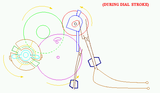
(b) and since the plunger doesn't interfere with the outer leaf , it continues to move along with the inner leaf, thus maintaining contact throughout the
dial stroke . The inner leaf ofcourse maintains contact with the cam and thus oscillates along with the rotation of the cam.
The dialling stroke is complete when the caller has turned the dial by the appropriate amount.This information is stored in the dialler spring and gets
converted into the electrical signal finally , to be sent to the telephone exchange
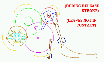
Next as soon as the caller releases the dial ,the
release strokecommences.As mentioned earlier , during this stroke the dial
is brought back to its original position by the torsional dial spring. This
rotates the main gear in the clockwise direction which moves the
transmission gearin the anti clockwise direction which in turn rotates the
cam gear
in the clockwise direction.This leads to the following:
(a) the plugger, which is located on thecam gear and linked to it by friction also rotates in the clockwise direction along
with the cam gear until it comes to its clockwise extreme position wherein it
fixes the position of outer leaf , constraining it.
(b) this leads to the making and breaking of contact between the leaves as explained in the "basic principle of impulse generation"
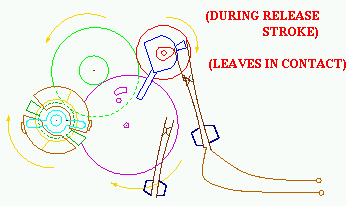
The amount of turn of the dial dictates the number of revolutions of the cam
gear and hence of the cam.�nd this guides the number of oscillations of the
innerr leaf and thus the number of pulses. And the accordance betwwen the number of dials and the pulses is maintained.
The release strokeis completed when the
knocker on the main gearknocks the plugger
to make it to rotate anticlockwise, thus releasing the outer leaf, bringing
the impulses to an end.Finally the release stroke is completed with the knocker separating "New number electrical leaves".Thus passing the information that
the process of dialling of digit is complete and hence bringing the dialling
mechanism to its original state,ready to accept a new digit in the form of a new dialling cycle.
Finallly to explain the role of the "reducer."The reducer is designed from
dynamic consideration.When the dial is released , during the release stroke
,it is the dialler spring that rotates the system.If allowed to unwind on its
own it would lead to the attainment of a high velocity(kinetic energy) by the
system leading to a more severe collision at the end of the cycle,leading to
greater stresses and quicker wear and tear.To avoid this is precisely the
function of the reducer.It essentially acts as a coloumb damper(friction
damper)and thus dissipates some of the enenrgy stored in the spring during the
release stroke.
It works as follows:
Motion is transmitted to the reducer by the reducer gear which is rotated by the transmission gear
which in turn is imparted motion from the main
gearThis gear train ensures that the reducers rotates at 24 times the
angular velocity of the main gear. At such a higher anguler velocity the
centrifugal force on the half discs, tends to move them apart, bringing them outward and thus leading to the pressing of the friction heads upon the metal ring,thereby dissipating energy in the form of friction.
BACK TO TOP