|
Scribe
Notes For
Lecture 32 (CS625)
by Amit Srivastava (Y0038)
amits@iitk.ac.in Date: Nov 11 2003
Multi Protocol Label Switching (MPLS) Circuit Switching Vs Packet Switching: In case of a circuit switched network a fixed amount of bandwidth is reserved as well as a route is chosen before a connection is established and only this route is used for the complete transaction on the connection. While in case of a packet switched network all the information is packaged into small groups called packets, frames, blocks, or cells. Circuit switching provides better Quality of Service (QOS) while packet switching utilizes the bandwidth more efficiently. Also, information about each and every connection needs to be stored thereby putting a limit on scalibilty. MPLS tries to combine the benefit of both the above switching technologies. It uses circuit switching within an ISP while packet switching is used within ISP's. Motivation for MPLS: Initially MPLS was developed to combine the benefits of internetworking and routing in layer 3 and layer 2 i.e. Network Layer and Data Link Layer. But, its major technological significance lies in implementing Traffice Engineering. Some Components of MPLS:
When an ingress recieves a
packet it encapsulates it inside a MPLS packet at layer 2 and passed on
to egress which then puts of
the MPLS headers.
 Fig 1
MPLS Packet Format
Fault Tolerance and Path Recovery Various path recovery
mechanisms are employed if some link goes down as shown in Fig 2
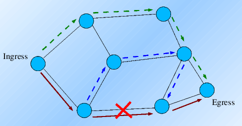 Fig 2 Local Recovery (blue broken line): A new path is chosen just between the two routers, the link between whom has gone down. Global Recovery (green broken line): A new path is chosen between the Ingress and Egress. Resources: |