Scribe notes on
MPLS and Traffic Engineering
Nov. 11,2003
Anshuman Panwar
Circuit Switching vs. Packet Switching
In circuit-switched networks, network resources are static ,a fixed bandwidth is allocated to a connection before the start of the transfer, thus creating a “circuit”. The resources remain dedicated to the circuit during the entire transfer and the entire message follows the same path. In packet-switched networks, the message is broken into packets, each of which can take a different route to the destination where the packets are recompiled into the original message. The telephone network is a good example for circuit switched network. In telephone network, bandwidth is reserved for a call at the start of the call.
As circuit switching is more related to bandwidth reservation, it gives a better support for Quality of Service (QoS).
Circuit switching results in better multiplexing.
Packet switching is used to optimize the use of the bandwidth available in a network and to minimize the latency.
Lookup is faster in circuit switching because it is a simple array lookup while in packet switching, longest prefix matching is used which is much complex and requires much complex data structures.
MPLS (Multi Protocol Label Switching)
Motivation:
In order to meet the growing demand for bandwidth, Internet service providers (ISPs) need higher performance switching and routing products. Although most carrier and service provider core networks run on impressive asynchronous transfer mode (ATM) backbones, most connections to these providers continue to be slow point-to-point connections, introducing latency and sometimes bottlenecks at the edge access points. In destination based forwarding, traffic engineering is very difficult and also traffic engineering should be independent of the link layer. All of these needs can be met with multi protocol label switching (MPLS), because it integrates the key features of both Layer 2 and Layer 3. Most importantly, it is not limited to any Layer 2 or Layer 3 protocol.
MPLS Basics:
MPLS layer works between layer 2 and layer 3 i.e. link layer and network layer.
MPLS does label switching.
Every IP flow is assigned a label.
MPLS direct a flow of IP packets along a predetermined path across a network. This path is called a label-switched path (LSP).
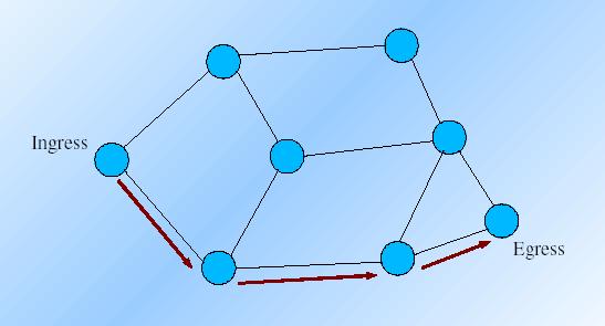
Figure 1 : Label Switched Path
When an ingress
router receives an IP packet, it adds an MPLS header to the packet and forwards
it to the next router in the LSP.
The labeled packet is
forwarded along the LSP by each router until it reaches the tail end of the LSP,
at which point the MPLS header is removed and the packet is forwarded based on
Layer 3 information such as the IP destination address.
MPLS Header and Packet:
MPLS Header
| Label (20 bit) | Cos(3bit) |
S |
TTL(8-bit) |
| L2 Header |
MPLS Header |
L3 Header |
L3 Data |
|
L2 Header |
MPLS Header |
MPLS Header |
L3 Header |
L3 Data |
MPLS Header's total size
is 32-bits.
Label (20-bit) : This is
the label per flow
CoS (3 bits) : Class of
Service
Stack bit: Indicate
the presence of Label Stack.
TTL(8-bit): Time To
Leave.
Fault Tolerance:
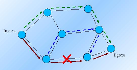
Figure 2: Fault tolerance in MPLS
MPLS is robust to link failure and recovers from the failure. It uses two kinds of recoveries to recover from failure
Local Recovery: Following the blue path. In local recovery a new path is adopted between the two routers, the path between whom has damaged.
End to end recovery: (The green path) Adopting a new path between the ingress and the egress. End to end recovery better in protection.
The failures are discovered by continuously monitoring the Hello packets.
Lambda MPLS
References: